Glenn Goldfinch's restoration photos of 93-895
March 2012 to ??
Glenn’s Red Buckle Progress Record – Part 1
Preamble
Being quite tall, I find a Buckle a little snug with my head brushing the head lining and my knees fouling on the steering wheel. As a result, I decided to investigate the possibility of lowering the floor in my Buckle to create a little more room. I prepared a CAD drawing showing my intention and then set about finding a RMS accredited engineer who would work with me to prove the suitability of my design. It took a few months to find someone not too far from my house, who also had the time to devote to the project. After a couple of meetings with an engineer from Rockdale I gained a clearer understanding of the RMS requirements and set about adjusting the design to increase the torsional rigidity. Modified chassis’ are now required to undergo a torsional test as part of the approval process.
The design eventually met with the engineer’s approval and I then set about procuring the materials for construction. I had acquired a rigid trolley some time back that had been built as a platform for the construction of truck bodies. I had recently used it to carry out some repairs to a Bolwell Nagari chassis and it proved quite useful. I intend to modify this trolley so that it can be used as a jig to build the Buckle Chassis on. This trolley has fixed casters on the centre of each side and a swivel caster at the centre of each end. In addition it has fixed casters on each corner that are just clear of the floor but will help to stop the trolley tipping when wheeled over uneven surfaces.
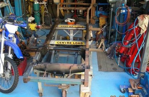
Buckle chassis sitting on truck body trolley
Friday 28 November 2014: I started work on the Red Buckle today. First job was to remove the 4 wheels from the corners of the build trolley. I cut these off with an angle grinder, leaving the caster base plates. This left four plates with mounting holes that I can use to secure the trolley to my floor plates to provide a stiff platform to weld up the chassis. I then lowered the chassis from the overhead beam and placed it on the trolley. After untying the bonnet I secured it to the chain block hook and hoisted it back up and out of the way. I then fitted the front braces (from the Nagari build) to the trolley but will have to make new braces for the rear.
Monday 15 December 2014: The trolley is now bolted to the floor plates and levelled. I fabricated 6 pairs of saddles using a former and my shop press and these will be used to clamp the 3rd cross-member and the rear chassis section tubes to the trolley frame. I have made plates to secure the chassis fixing brackets to the trolley and secured a 50 x 50 SHS across the trolley beneath the 3rd cross-member. This has been secured to the cross-member with fabricated saddles welded to the SHS via 50 mm SHS spacers.
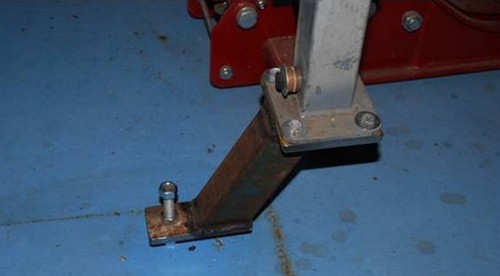
Corner of build trolled secured to steel plate set in the concrete floor
The body was then refitted to the chassis to ensure that the angle of the rear chassis section matched that of the boot floor. The chassis was drooping slightly at the rear so I propped it both sides with wooden blocks and a couple of metal spacers. The body now fits nicely on the chassis and I can now make up the fixing brackets for the rear of the chassis. I suspect that the rear of the chassis was bent slightly due to the 1” braces being improperly fixed at their forward end. They had been modified to accommodate telescopic shocks and were secured at their lower end with flat bars at right angles connecting them back to the chassis. This allowed them to move forward and not provide the necessary support to the back of the chassis.
Monday 12 January 2015: I finished off the chassis jig today. The chassis is now clamped with saddles at the ends of each of the cross tubes and twice along each of the rear tubes. Additional tabs locate the rear leaf spring mounts and both of the rear square cross members. I have used spacers under some of the mounts to allow adjustment for the metric sizes of the RHS and SHS. I also placed spacers under the fixture for the 63.5 mm cross member to allow for the bend in the outer parts of the tube caused by welding of the front leaf spring mounts. I‘m hoping that I can minimise this bending by clamping the ends of the tubes when I weld in my spring hangers.
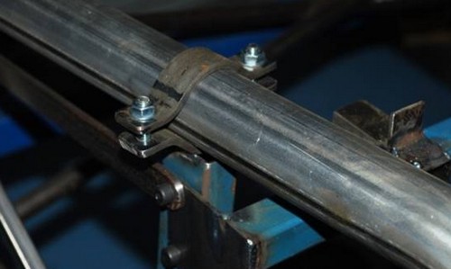
One of the clamps used to secure the chassis to the jig
I’ve also fixed blocks on the outsides of the main rails to align them on the jig. The final job on the jig was to make supports for the 63.5 mm (4th) cross member. These are similar to those made for the 3rd cross member but required fabrication of a larger pair of saddles. I made up another former and used the press to make the parts.
Tuesday 13 January 2015: Today was a real bust. I set up my Thiel mill to notch the chassis tubes and using a holesaw in the drill chuck just didn’t work. The drill chuck doesn’t take side thrust and the holesaw chattered really badly, eventually moving in the chuck jaws. The holesaw has tungsten carbide teeth and the arbour is part of the saw. I could use a conventional holesaw but that would mean making an arbour that would fit in one of the mill collets. I may do this in future but don’t want to spend the time at the moment. I then pulled out my JD Squared “The Beast” notcher and spent some time looking at how it could be used for this work. It’s made primarily for round tube but can clamp square or rectangular tube but provides no convenient way to position the tube accurately. I decided to sleep on it and see if I could come up with a solution overnight.
Wednesday 14 January 2015: Today I tackled the notcher modifications. I worked out that I could fit a piece of angle into the grooves provided in the notcher that align round tubes with the notch cutter. I made the guide from a piece of 50 x 50 x 6 aluminium angle machined to fit the width of the uppermost groove. This was 48.5 mm wide so I only had to trim a couple of mm off using the milling machine. Once this was done I trimmed the other side of the angle down to 25 mm and it all fitted pretty nicely.
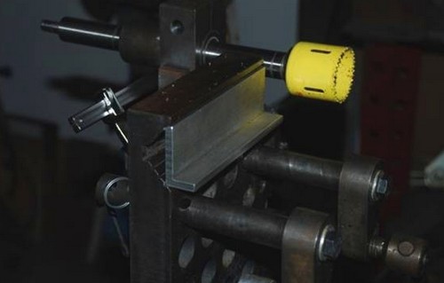
Aluminium insert in “the Beast” notcher for square and rectangular tube
The modification had taken most of the day so I didn’t make the first trial until late in the afternoon. It took a bit of time to get the cutter positioned central to the RHS but now that this is done I can cut multiple notches with minimal setup. The resultant notch was quite quick to do and the finish was very good. The notch is well centred and tangential to the sides of the RHS. I’m quite pleased with the result. I then went to make the first of the chassis tubes but couldn’t find the pieces of SHS that I had bought for these parts. I made a quick trip to the steel merchant and managed to find a couple of pieces in his scrap bin that I got for $7.00. Once back home I notched both pieces in no time and the results were fantastic.
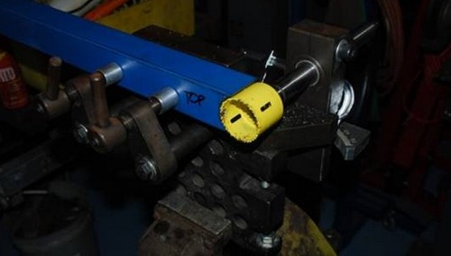
Notching the upper part of the chassis rail
Thursday 15 January 2015: Today was a good day. I set up the main chassis rails in the notcher and cut the notches in the ends of the rails. Getting the rails centred on the cutter and square to its axis took a little time due to the weight and length of the rails but the end result was worth it. I set up the cut so that the sides of the 4mm thick rails would be trimmed down to 1.6mm, to match the thickness of the rear tubes and achieve a nice result.
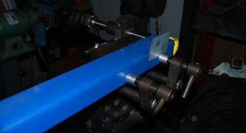
Notching the main chassis rail
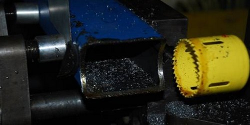
Notching the main chassis rail
The next job was to cut the two holes through each chassis rail. I started with the 2” holes. I wanted to keep the holes close to the cross member diameters so I decided to use a pair of carbide toothed hole saws that I had for this purpose. Normal hole saws run out quite a bit. Unfortunately these don’t fit the notcher so I “borrowed” a small drill chuck from my lathe and fitted this to the notcher spindle. Because of the combined length of the chuck and hole saw I needed to space the rail away from the notcher frame and used a couple of parallels for the purpose. I had quite a bit of trouble setting the rail so the hole would be in just the right place, so it took me nearly an hour to get it right. The cutter chattered quite a bit making the hole but the end result on the first rail looks good. Tomorrow I’ll tackle the next rail.
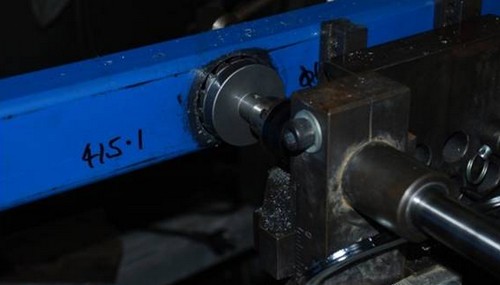
Machining one of the cross member holes in the main chassis rail
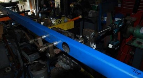
The completed hole in the chassis rail
Friday 16 January 2015: I completed cutting the cross member holes through the chassis rails but still experienced quite a bit of chattering from the hole saws. I changed from my big electric drill to my battery drill as the drill speed seemed better suited to the job. Chattering was much reduced but still an issue. I tried various combinations of speed and pressure and settled on a moderate speed and low pressure at the beginning of the cut and a higher speed and low pressure once the hole was well established.
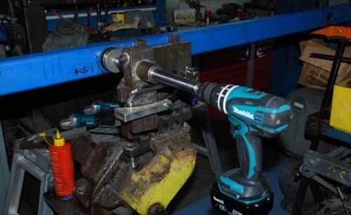
Another view of the machining setup
Once the holes were completed I spent the remainder of the afternoon marking up the mitre cuts on the upper and lower chassis rails.
Saturday 17 January 2015: I mitre cut all the chassis rails and then set them up in their final positions to check the result. The two rails match very closely and the holes on both main rails for the cross members align perfectly. I spent a lot of time marking up the holes positions, checking and rechecking to ensure they were correct and then did the same when setting up the rails in the notcher. It was a big relief when I placed one rail on top of the other and the holes matched precisely.
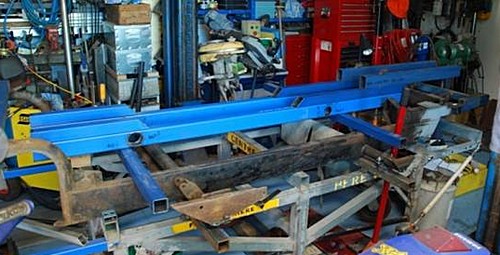
Chassis rail components after completion of the machining
Thursday 22 January 2015: Today I removed the original Buckle chassis from the jig and hoisted it up out of the way. I then placed the machine chassis components in the jig to check how they fitted and aligned with each other. I found that the main rails and the front horns fitted beautifully but the rear, round tubes will require just a little reshaping. I spent the afternoon TIG welding plates over the front of the rear upper rails and the rear of the front upper rails. This work came out nicely and will weld plates over the rear of the horns tomorrow.
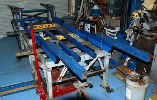
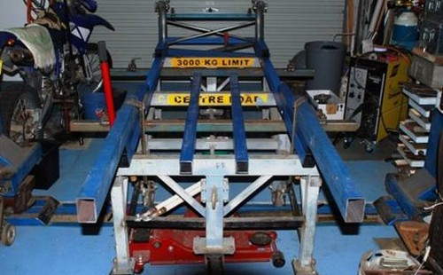
Trial fitting of chassis components on the chassis jig
************************************************************************************
Mystery Buckle.
Now it is registered, we have checked it out with the NSW RTA and it comes up with a incorrect chassis number.
I have now sighted this car. It is a REPLICA build with no Buckle Motors body and chassis numbers.
It is NOT the stolen or missing BUCKLE
We will decide where to list it in the website asap.
****************
Now your restoration is finished,
BUCKLE UP AND DRIVE
